
64-point Light Board
Catalog Item 767A
128-point Light Board
Catalog Item 768A
Light Fibers
Catalog Item 858
AutoBuild Software
Catalog Item 728
AT&T Natural Voices Voice Font
Catalog Item 792
Request Prices
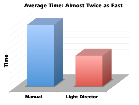
| CableEye M3U with CB37 Light Director Board Our Guided Assembly Light Director™ system (patented) provides a new, computer-guided technique for assembling connectors used in aerospace, medical, and other high-reliability applications. This system uses light fibers driven by super-bright LED lamps to individually illuminate target cavities in the connector being assembled. When the technician enters the wire code printed on unconnected wires, or touches a wire connected at the other end, the CableEye software turns on the appropriate fiber, thereby causing a bright, flashing light to project from inside the target cavity guiding the technician to the proper insertion point. Correct insertion is confirmed by the elimination of light from that location, whereas insertion into an incorrect location leaves the flashing light visible. Normally, technicians crimp pins on wires in advance of assembly to the connector. Wires may be identified during the assembly process by numeric code, bar code, color code, or if no codes are present, by electrical detection using a wrist-strap if the far end of the cable has already been assembled and can be electrically connected to the system. Field testing has shown that the Light Director doubles assembly rate over manual methods while nearly eliminating errors. Because the Light Director greatly reduces the perceptual challenge of manually locating pin cavities in a complex connector, technician fatigue is greatly reduced, permitting a continuous, high productivity rate throughout the work day. The Light Director™ system is an accessory for CAMI's CableEye® PC-Based cable test system. Customers purchase a mounting kit for each mating connector consisting of a CableEye plug-in board with special LED sockets, LED light fibers, fiber guide boards, a connector support board, and hardware kit. All parts are reusable. Requires the AutoBuild Guided Assembly Software (Item 728). |
|
Synthetic Speech
The Light Director also employs high-quality synthetic speech in English, Spanish, or French to read the pin number to the technician, further reinforcing the target location.
Speech recognition is also available as an option permitting the technician to read wire codes to the system, thus eliminating the need for a keyboard or monitor.


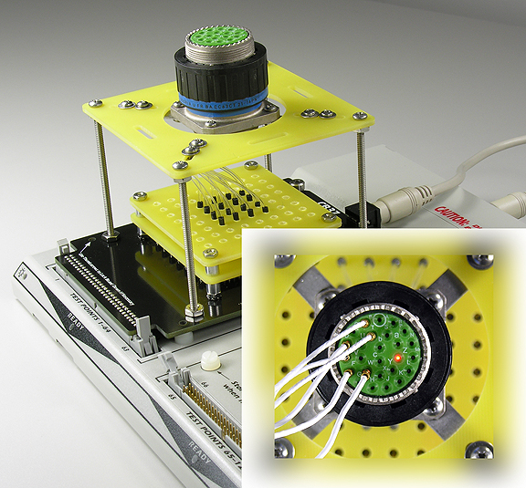
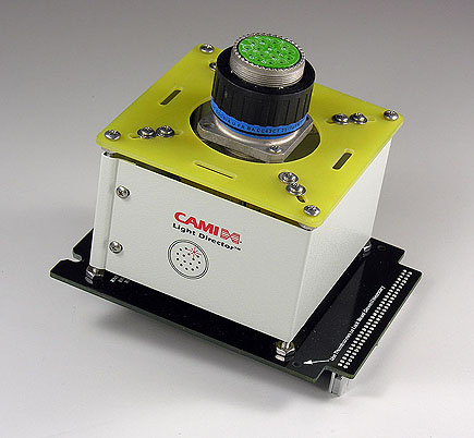
CB37 Light Director Board
with 55-Pin Connector
Mounted and Ready to Use
In this photo, you see a 55-pin mating connector mounted to a CB37 board. The CB37 can handle connectors of up to 64-pins. The CB38 board accepts connectors with up to 128 pins.
Once trained, a technician can assemble one of these boards in 60 to 90 minutes, an amount of time that will be earned back during the first day of use in improved productivity. The rugged support structure will be maintenance free, and the mating connector will not wear out because no pins are present (just light fibers which never touch the assembly piece).
When a project ends, you may if you wish easily disassemble the board and reuse all parts for another project. Alternatively, the board may be unplugged from the tester and stored for future use.
Space in front of the board may be used to label this unit either by connector, cable, or customer.
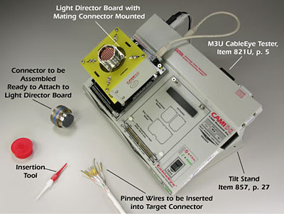
Light Director Setup
In this photo, the board above is mounted to the CableEye system and ready to use. The connector to be assembled is on the bench along with the pre-pinned wires ready to be inserted. In this case, each wire is numbered to correspond with a printed insertion list.
If assembled manually, the insertion list would tell the technician which cavity number should receive each numbered wire. The technician would then carefully locate the cavity, sometimes counting forward or backward from a reference location, and insert the pin into this cavity. During manual pin insertion, locating the correct cavity takes time and requires the technician’s full concentration.
Using the Light Director system, the technician simply looks for the cavity with a flashing light and inserts the pin there. Neither reading cavity numbers from the target connector nor counting forward or backward from a reference position is necessary.
This reduces the perceptual challenge in finding the target, and therefore speeds assembly, improves accuracy, and reduces the fatigue level that would be experienced after several hours of work.
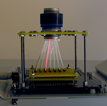
Side View Showing Fibers Entering Mating Connector
Here you see 1.5mm diameter fibers entering a 26-pin mating connector. For connectors with larger pin counts, a 1mm fiber would be used for greater flexibility.
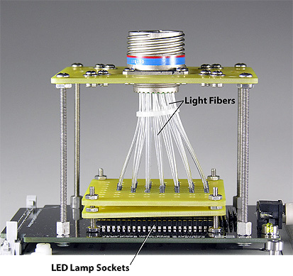
The light path may be viewed in a dark room. Because the light source is a high-brightness LED but not a laser, the light can be easily seen without any distortion or eye strain.
View Into Workpiece During Assembly:
Flashing Cavity Shows Target Pin
The light flashes about five times per second. Flashing helps identify the target cavity in the presence of ambient light and previously inserted wires.
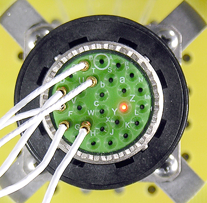
Moisture Plugs
Prior to pin placement, we illuminate all cavities requiring moisture plugs to allow rapid plug insertion. Blocking cavities not requiring pins further reduces the chance for insertion error.
.jpg)
Flexible Light Fibers
Our Rayon™ light fibers flex easily to accommodate widely varied connectors. Longer fibers permit more convenient assembly and readily coil under the connector when the fixture is secured.
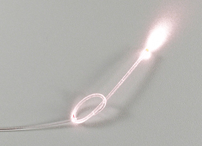
The fibers are extremely flexible allowing us to use long fibers to ease assembly and then bend them out of the way when the mounting plate is attached.
.jpg)
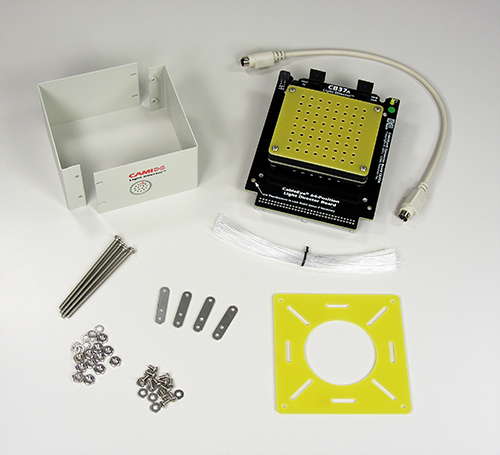
CB37A Mounting Kit
Each CB37A mounting kit includes an assembled light driver board, connector support plate, support hardware, light fibers, fiber shroud and power cable. All parts are reusable.
A connector graphic, an assembly sequence, and voice prompts support the Light Director to provide backup information for the operator. All insertion steps are logged in the event of power failure or computer malfunction, so that the build can resume when a normal operation status is re-established.